Pin on mic wireing 35 mm stereo wiring diagram electronic circuit projects electronics basics electronic schematics audio jack wiring diagram bookingritzcarlton info instalacoes eletricas eletrica all details about cb microphone wiring cb microphone microphone cb mic making a 4 pole trrs to 3 5mm stereo mic adapter male to 2x female from an. (b), but there is another set of wires d, e, f.

Usb Microphone Wiring Diagram at Wiring Diagram
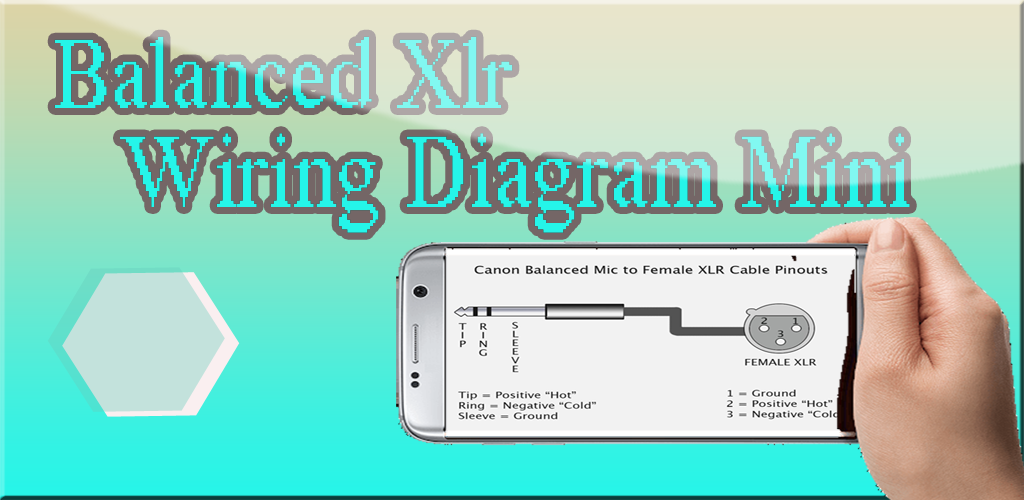
3 pin xlr connectors are standard amongst line level and mic level audio applications.

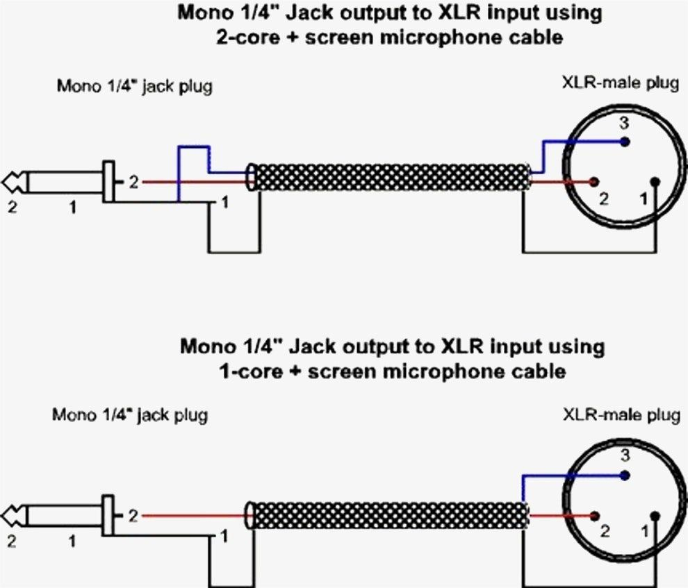
3 pin microphone wiring diagram. Still used on musical equipment (especially in electric guitars) and aviation. 3 pin xlr wiring diagram, cable wiring, etc. cable designed for being cut into standard mic cables may have 2 pairs of wire and a shield around the outside, in that case pair the colors together and make sure they go to the same pin number on each end. Xlr pin 2 = low impedance audio hot (amphenol pin 4, white wire, typically) xlr pin 3 = low impedance audio return (amphenol pin 3, black wire, typically) note:
You will get same sound from both the sides. The main wiring is the same a fig. Below is the pinout of ts type male audio jack.
Generally, pin 2 or positive pins are connected with a red wire, pin 3 or negative pins are connected with a black wire, and pin 1 or ground pins are connected through shielded wire. Microphone wiring diagram diagrams www walcottradio com copper talk turner m 2 u for 4 pin cobra uniden qrz forums 11 most por mic resource detail the dxzone microphones plus three or astatic d104 m6c mike guide unlabeled resistor ssk schematic worldwidedx radio forum rci 2950 radioaficion vhf transmitter 5 input jack 251 date co crystal. Not following the details will cause your household harm.
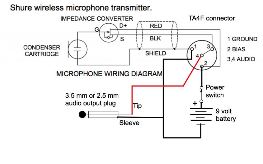
Standard 5 pin wiring 148 gtl, 2000 gtl, etc. The mic you have is here: The other end of the dc supply (0v) connects to the case pin.
Ts type male audio jack. Usually this set is used to switch voltages from receiver to transmitter. On the four pin amphenol, pin 2 is a high impedance, unbalanced output.
The other pin is the output/bias point. Collection of xlr to mono jack wiring diagram. If the original mic wire is being used then :
Tx (black) goes to pin 3 on the mic plug. Imho, you should never use color to wire a mic. The rear view is the end you solder from here are the connections on each pin.
Here, you can see the wiring and connection between a male connector and a female connector. A certain wire has an appropriate pin number that is necessary to be followed. Connect a resistor between 1k and 10k betweeen the bias point and a dc supply (say 5v).
Xlr connector wiring and connection diagram. Shure microphone 4 pin microphone wiring diagram hand mic for ft b inside 3 wire microphone wiring diagram by admin through the thousand pictures on the web concerning 3 wire microphone wiring diagram, picks the best series together with ideal quality only for you all, and this photos is among pictures selections in our best photos gallery in relation to 3 wire. 3 wire microphone wiring diagram with regard to 3 wire microphone wiring diagram by admin through the thousands of pictures on the web in relation to 3 wire microphone wiring diagram, we choices the very best libraries along with best resolution exclusively for you all, and now this photos is usually one of photos choices in this finest images gallery.
Xlr pin 1 = shield, amphenol pin 1. The above diagram shows you the pin numbering for both male and female xlr connectors from the front and the rear view. These types of audio jacks does not support stereo sound and microphone, which means there is no left and right.
Voltage is on wire e, then e, d will supply voltage to receiver.

SHURE TA4F signaling 1 ground 2 +5VDC 3 signal 4 20K to
Xlr Mic Cable Pinout umbsheet

Sennheiser Xlr To Mini Cable Wiring Diagram

3 Pin Mini Xlr Wiring Diagram / Microphone And Wireless

Wiring Color Diagram On A Usb Microphone USB Wiring Diagram
Mini Xlr Wiring Diagram Astell Kern 5 Pin Mini Xlr To 3

3 5 Mm Stereo Jack Wiring Diagram 4 Pole Wiring Diagram

Dynamic Mic Xlr Wiring Diagram
Xlr Wiring Diagram Doctor Heck


How to Wire an Unbalanced Microphone To A Balanced XLR

[MY_5058] Astatic D 104 Microphone Wiring Moreover 4 Pin

Mini Xlr Connector Wiring Diagram 3 Pin Xlr Connector

3 Pin Mini Xlr Wiring Diagram / Microphone And Wireless
Dell 3 Pin Trs Connector Wiring Diagram

Making a [4Pole TRRS to 3.5mm Stereo & Mic Adapter (Male

Usb Microphone Wiring Diagram at Wiring Diagram

Xlr Wiring Diagram / Diagram Usb To Xlr Wiring Diagram
Mini Xlr Wiring / Stereo 3.5 To Male Xlr Wiring Diagram

Mini Xlr 4 Pin Wiring Blackmagic Forum View Topic Pinout


